F3A & F3B -
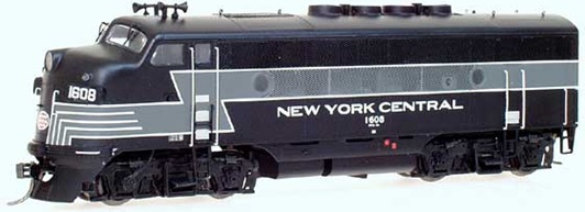

F3A & F3B -


F7A & F7B
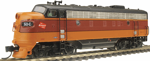

Introduced: 2005 (F3A / F3B), 2006 (F7A / F7B), 2014 (revised F7) and 2023 (DCC-equipped F7)
Intermountain has made a nice little niche for themselves with their line of nice looking and fine running EMD "F" units. The first release of F3 and F7 models came out on the heels of their successful FT models of 2002. Both the F3 and F7 share the same exact chassis / mechanism, so to save myself some time I'm going to cover them both here. Note that the F7 chassis was completely redesigned in 2023 when support for DCC-Sound was added.
I've been told that the shells are designed, cut and molded in the USA. They are then finished and drives put under them in China. A and B units are sold separately (both powered).
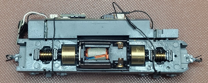
The original version sports all of the niceties one normally associates with "modern" diesel models, EG - split-frame DCC-Ready metal chassis, dual-flywheels, low-friction drive, plastic truck assemblies, plastic gearing, blackened wheels, all-wheel drive / pick-up (no traction tires). The motor is an open-sided 5-poler with skew-winding. Wheels are low-profile and have no problems on Code-55 track. Couplers are chassis-mounted Accumates. Directional lighting on A units is controlled by a PC board mounted on top of the chassis, and with the LED headlight mounted on the front of the chassis (with wires running between the two). The headlights are white and very bright. In the above picture, I've swapped out the stock PC board in favor of a Digitrax decoder.
These may be the most gorgeous looking and sweetest running F units I've ever encountered. Mine are absolutely dead quiet, silky smooth runners. Slow speed creep is tremendous, pickup is perfect and they pull a ton. The looks are equally impressive, and I especially love the etched metal grills and fans. The separately applied handgrabs are a nifty feature as well.
One minor complaint I have with these models is the fact that the headlight on the "A" units is not part of the PC board (rather, it sits about an inch away from said board and is connected via a couple of wires). No big deal if you're operating these in DC mode, but it does make decoder installation a bit more complicated than it could/should be (basically involving desoldering the light wires from the stock PC board and then resoldering them to the decoder board). My other minor quibble is with the side screens on the F7 models. These are extremely easy to dislodge (and not particularly easy to reinstall). So be extra careful when handling them.
Note # 1 - Prior to the 2014 production run, these locomotives accepted a "drop in" style decoder. In this scheme, the motor brushcaps had lengthy metal tabs that legs on the PC board (or decoder) would contact in order to transfer current to the motor -

Unfortunately, as of 2014 the legs and brushcap tabs were removed. Instead, what we have are wires soldered directly to the brushcaps (and then running up to the PC board) -

Identifying the newer (and less DCC-Ready) version is easy. If you see wires on top of the PC board, you have the newer version -

Only Intermountain knows why they decided to take this giant step backwards DCC-wise. But whatever the reason, decoder installation is now going to require even more soldering (desoldering the motor wires from the PC board and then resoldering them to contacts on the decoder board). Digitrax's DN166I1D decoder is designed for these new models.
Note #2 - The first run of F7s contained an error with the "B" units whereby the roof and sides were put together in the wrong orientation with one another. Intermountain has since fixed the problem and will exchange any faulty units with the corrected version.
Note #3 - Occasionally one will encounter an Intermountain F unit that makes a lot of noise when running. Ron Bearden (noted locomotive guru) has diagnosed the problem as being too much space between the "spiked donuts" in the drivetrain (one donut mounts to the wormshaft, one mounts inside the flywheel, and then a slotted cylinder connects the two).

The noise problems arise when the donuts are mounted too far apart from each other (thus allowing the connecting cylinder to rattle around as the driveshaft spins). And the simple solution is to close the distance between the two donuts by sliding the wormshaft donut further out on its shaft (IE, towards the flywheel).
| Stock Donut | Relocated Donut |
 |  |
When moving the wormshaft donut, be sure to move it such that most (but not all) of the slack between it and the connecting cylinder is removed. Without a tiny tiny amount of wiggle room between the various parts, a slight bind will be placed on the drive train and the noise will be back.
As noted above, the F7 chassis was completely redesigned in 2023 (with DCC-Ready, DCC-Quiet and DCC-Sound F7's being part of the release). Apart from some changes to the detailing, the new and old shells are essentially the same and can be freely swapped between either chassis. Unlike the previous version, these new models have working backup lights (provided by an LED board mounted on the back to the chassis). Similarly, the old free-floating headlight bulb has been replaced by an LED board that mounts to the front of the chassis. Said board also provides separate lighting for the MARS light and numberboards. Both LED boards are wired to the main PC board. A Next18 socket on the main PC board serves as the mount point for the decoder (either sound, non-sound or a dummy plug, depending on which version you have). The PC board and various decoder boards are all made by ESU.
DCC-Sound F7A -

DCC-Quiet F7B -

DCC-Ready F7B -
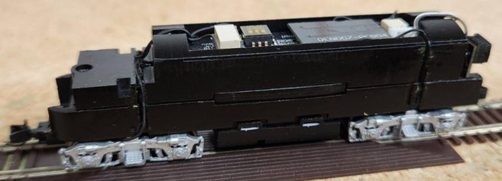
The PC board has a set of dip switches that are bit of a mystery until you remove the decoder to reveal the instructions. As pictured below, said switches determine headlight and MARS light behavior -

For the sound-equipped models, the speaker is mounted inside of the chassis, just above the fuel tank detail. The speaker is an 11 x 15 mm "sugar cube" type. Sound quality is fine and pretty much on par with most of the other N scale sound models out there.
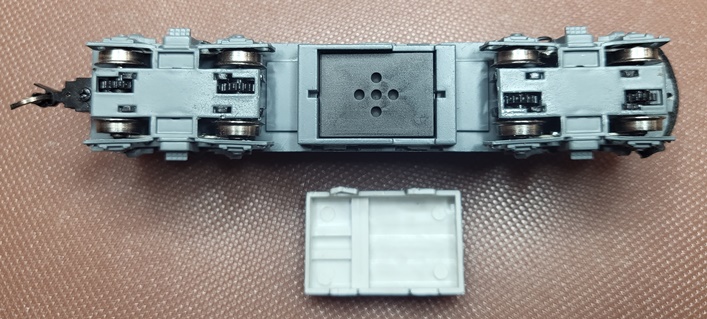
The internals are pretty much the same as before. Metal strips from the brushcaps and speaker (if there is one) rub up against contacts on the bottom of the main PC board. Three screws hold the PC board to the top half of the chassis. Two more screws hold the two chassis halves together. The main change is that current is now ferried to the main PC board via wires (as opposed to the old sprung chassis strips of yore).
These new models are every bit the equal of their predecessors, if not better. My A/B set ran flawlessly right out of the box, and continued to flawlessly over a week of continuous operation. Smooth, whisper quiet, great slow speed creep, and with pulling power to spare, there's just nothing to complain about here. The added lighting features are a great upgrade, and new details like windshield wipers are a welcome addition. And for the nitpickers out there, they've somehow managed to lower the fuel tank about 1/32", so there's not quite as much daylight visible between the rails and the bottom of the fuel tank. Just a really great job by IMRC on this one.
Shell Removal -
To remove the shell, start by inserting two toothpicks (or whatever) between the shell and chassis at the center of the fuel tank. At this point the shell should pull up and off fairly readily. Just make sure you're pulling straight up (rather than favoring the front or back), otherwise it will likely get hung up. For "A" units, you'll need to remove the front coupler first (just unscrew the screw and slide the coupler out the front of the pilot).
Grade: A (for all)