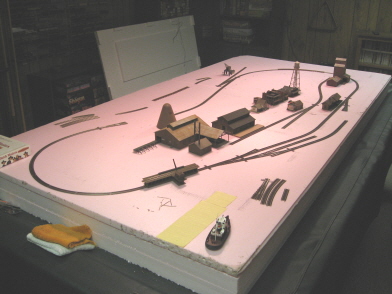
01/07/08 - Layout construction begins

For my base, I decided to go with a sheet of 1" thick foam (the pink stuff) sitting atop two sheets of 2" foam (all 8' X 4'). I'll eventually be carving sections out of the top sheet for the lakes, as well as carving all the way down into the middle 2" sheet to create a deep gorge for my timber trestle (trestles?) to traverse. And since my last layout wound up being way heavier than I would have preferred (what with it's frame being built out of 2 X 4's), I decided to add the third sheet of 2" foam as an eventual frame. IE, once I settle on a size, I'm going to cut huge chunks out of it, thus giving me some open space underneath the base where I can mount my various electronic gizmos and run all the wiring. I've never heard of anyone doing anything like this before, so here's hoping it all works out.
Once I started laying track, the first snag I ran into was trying to find a logical place for the log dump. And as it turned out, the only really workable place for it to go was right on top of the sawmill's log loader. And since that would've wound up looking really stupid, I decided I needed to flip the whole layout plan 180 degrees. This allowed me to also flip the mill, thus relocating its conveyor to the opposite side of the log pond (and away from the dumper).
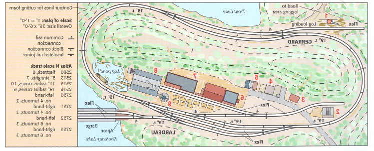
Converting this track plan from Code-80 to Code-55 is turning out to be quite a challenge. There isn't a one-to-one correspondance between any of the various pieces of track, and overall the Code-55 seems to be geared much more towards sweeping track plans. The upshot of all that seems to be that there's no way I'm going to be able to confine this thing to a 6' X 3' base. Well, no problem there I guess. I certainly have plenty of room to work with. Although I'd definitely prefer to keep this baby confined to something like 7' X 3.5' (or thereabouts).
As things have started to take shape, I now see a few opportunities for a few additional structures. It looks like there might be some room for that "Valley Lumber Yard" building after all, so I think I'll go ahead and build it and see what I can do with it. Also, I think a nice big loading dock for the track side of the transfer building is in order. And lastly, I think a steam-era water tower would go very nicely over by the freight and passenger facilities.
01/08/08 - A couple more structures
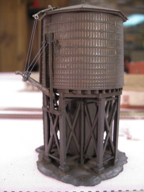
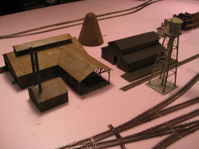
For my water tower, I decided to go with Bachmann's "Plasticville" pre-built. And despite the kindergarden brand name, I actually think this is a pretty nice looking structure (cheap too). Unfortunately, job one was dealing with Bachmann's simply craptacular "the circus has come to town" paint job. Mauve, yellow and black? I mean, come on. I don't know what planet the Bachmann "art department" lives on, but up in my neck of the woods all of the surviving steam-era water towers are basic brown from stem to stern.
So yeah, I handbrushed the tank (top and sides) with Floquil "Roof Brown", sprayed the supports "Grimy Black" and then Bragdonized the thing from here to next week.
The paint insanity thus addressed, I then decided that the fluffy, lame-ass spout support strings needed to go as well. And so, away they went - replaced instead by Berkshire Junction "EZ-Line" (the same stuff I use for telephone pole wires).
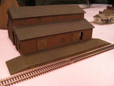
For my transfer building, I purchased a Heljan "Freight and Passenger Platform" and basically discarded 90% of it. Yeah, kind of a waste, but it didn't cost much and the platform itself was exactly right for my needs. What I really wanted was a wide and long dock where I could (eventually) pile up a Bunch-O-Lumber-Waiting-To-Be-Loaded, and this was the only structure I could find that really filled that particular bill.
As far as the nuts and bolts of the whole operation goes, not much to report here - I took two of the dock pieces, shortened one of them so that together they fit the transfer building, glued everything together, painted everything with Floquil "Rail Brown" and then went nuts with the weatherwash and Bragdon.
So, that's about it. I'm still working on Model Power's (ahem) "Lumber Yard" kit. And well, we'll see what happens there... (foreshadowing: I am not optomistic).
01/09/08 - Finished the first mock-up
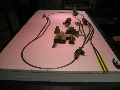
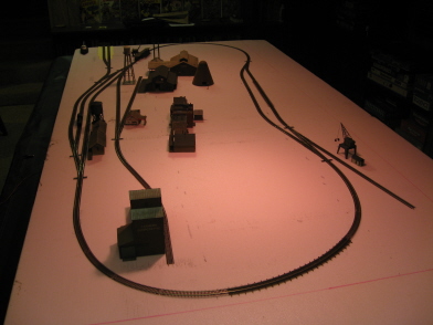
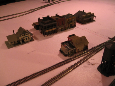
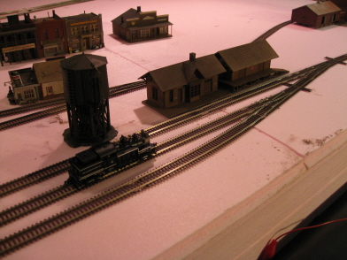
When it comes to prepping for track-laying, I've never had much luck coming up with detailed track plans of my own. Frankly, I just don't have the brainular wherewithal to look at a 2-D rendering and envision how it's going to work in 3-D reality. So, I've always just started out with vague ideas about what I want and then started laying track in trial and error fashion (looking for what works and what doesn't). Unfortunately, this "method" basically precludes the use of that most basic of track laying staples - the flex track (sproing!)
Now, I thought I was going to be able to avoid the whole "make it up as you go along" thing this time around by going with somebody else's track plan. But then I went all insane and decided to use Code-55 instead of Code-80 and found myself back in the same old "up the creek without a track plan" boat. So, once again resigned to having to figure out my track on the fly, I simply got on with it (hey, it's not painting the Sistine Chapel after all, fer cripes sake).
Now, back in my Code-80 days (way back three months ago) this whole process would've meant custom-cutting just a whole lot of track (because Code-80 has, what, three different curves and three different straights?) Well, fuggedabout it, those days are over. I've tried Code-55, and I tell ya brother, I have seen the light. I have no idea how many different types of C55 curves and straights Atlas offers, but it's one hell of a lot (and yeah, I bought at least one package of nearly every variation). And suffice it to say, I was able to mock up the whole layout without having to custom-cut a single piece of track. I mean, jeez, you could've knocked me over with feather!
OK, I spent way more money on track than I really needed to (basically winding up with enough to do two or three entire layouts this size). But hell, it's not like I'm not going to use it all eventually. And frankly, I think the benefits in flexibility totally outweigh the costs. Hell, given my new (and nigh infinite) supply of options, I no longer live in fear of the "now what the hell happened here" factor when it comes to turning a mock-up into actual glued-down track.
On the downside (and only a minor quibble), I did have some issues with a couple of pieces of track (18.75" radius curves mainly) where the plastic rail "spikes" wound up bleeding up too high on the insides of the rails. This resulted in a noticeable "rumbling" sound as I test-ran my Shay around. However, simply running a small file along the insides of the rails to brush off the too-tall spikes (a two second procedure) quickly solved that problem. So, a minor annoyance at best, and certainly nothing that's going to sour me on 55.
A more serious downside is the whole deep flange thing. You simply cannot run locomotives or rolling stock on this stuff unless they have low-profile wheelsets. Fortunately, my roster of rolling stock is pretty limited. So, converting those pieces that don't already have lo-pros isn't going to be that big of a deal for me. And what about locomotives, you ask? Well, once again not that big of a deal (at least as far as this particular layout is concerned). Given my locomotive collection (basically everything ever made), I'm sure I have plenty that are C55-ready (and will look at home operating on Shay Stadium). Still, I can see where this would become a major concern for people with large rosters of locomotives and rolling stock all needing new wheels.
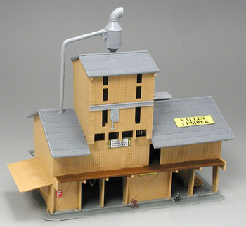
OK, so now let's talk about Model Power's (ugh) "Valley Lumber" kit...
I guess this thing is based on some sort of European prototype (allegedly introduced by Pola back in the 60's or 70's). And, I dunno, for some reason I actually thought it looked fairly benign when I first saw pictures of it (EG, the one above). Unfortunately, the kit itself turned out to be pretty awful- lots of bendy, warpy and flash-ridden pieces. And even leaving aside the "these molds should've been retired years ago" factor, the building itself is just plain ugly. The architecture is completely bizarre (the full reality of which is not adequately revealed in the above picture). And at the end of the day, it just plain don't have no business taking up space next to the rest of my fantastically gorgibeautious saw mill buildings. So yeah, I went ahead and banished it to the ol' kit-bash scrapheap.
So anyway, with my track finagling now behind me, it looks like I'm going to wind up with something like a 7.5' X 3.5' layout. A bit larger than I would have liked, but still workable. My main concern is still portability, but since I won't be adding any really tall features (like backdrops, for example), I think I can get away with the extra length.
However, given my overall bigulation of the original Kootenay plan (a side affect of the switch to 55), I'm now thinking I should probably add a couple of more buildings to the mix. And seeing as how I've gotten over my fear of wood, how about a couple more AMBs? I think some sort of railroady building over by the Plasticville water tower and then maybe some sort "main street" type building over next to the gas station would probably look good. Anyway, we shall see...
01/14/08 - Finished the car float (almost)...
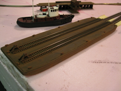
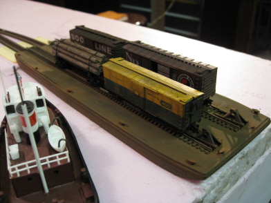

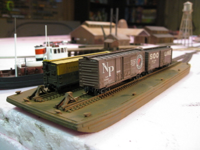
This baby started out life as a Sylvan Scale Models "Railway Car Float". And although a fairly decent model as delivered, it did take a bit of tweaking in order to make it Stadium-worthy (and with more modifications to come). But don't get me wrong, I'm not complaining (not more than usual, anyway). This is the only game in town as far as car floats go, and it was either this or (yikes) scratchbuilding one.
First off, it's way too long for my purposes (16"). But no worries there - I knew going in that I'd have to resize it to fit this layout. What turned out to be a big surprise was the actual composition of said model. Based on previous Sylvan boats I've purchased, I expected a gigantic chunk of cast resin. However, once I pulled it from its package I discovered that it actually consisted of two rather ill-fitting and flimsy pieces of resin - a hollow hull and a thin deck.
So, first things first, I chopped about six inches worth of car float out of the middle. Then I spent a good deal of time sanding and finagling the four pieces (two hulls and two decks now) such that all (or at least most) of the various seams went together smoothly.
Once I got all the pieces to more or less fit, I then went ahead and glued everything together (or rather, CA'd everything together - regular model glue just plain don't work on this weirdo resin stuff). However, at this point I decided that the end result looked and felt too danged flimsy. So, in a moment of Mediocre Modeler inspiration, I came up with the idea of filling in the hull with Woodland Scenics Hydrocal. And amazingly enough this actually worked - providing just the right amount of heft and rigidity.
Now I had to decide what I wanted to do about rails. The deck actually comes with molded-in mounts where (in theory) rails could be fixed. However, the deck also (despite my best efforts) wound up being not entirely flat. So, going the glue-the-rails-on route would've netted me quite the roller-coaster. Worse still, I didn't have much faith in my ability to CA individual rails to the deck and maintain proper gauging. So, favoring reliability over prototypity, I decided to sand off the stock mounts and simply glue pieces of sectional track to the deck (ties and all).
So, reliability insured, I still had the problem of an uneven deck to deal with. I did try leveling things off via a bit of sanding, but that wasn't really getting my anywhere. So, my next bright idea was to fill the depressions in with a thin layer of Woodland Scenics Smooth-It (not unlike bondo-izing the old high school hot rod). Surprisingly, this worked out really well. And after a bit of smoothing, I had an absolutely flat deck on which to mount my track.
So, with track firmly in place, I then painted everything (Floquil Roof Brown), glued on the cleats and track bumpers (the former coming with the float, and the latter being Cornerstone prebuilts), and then applied the usual Bragdon malaise.
At this point I thought I was done. Then I looked at it for a while... Then I looked at it some more... And finally I decided that I just didn't like the look of those nasty old ties sitting on the deck of my otherwise nice looking float. Eventually my OCD kicked in and I was forced to address the situation. So, at the moment I'm in the process of adding a layer of planking to the deck. And by golly, you'll see the results of that whole operation, um, well, y'know... when I finish...
Oh, and how 'bout that way cool steam tug? I picked that baby up on eBay- assembled, painted and everything. The guy who sells them has a whole lot of nifty N scale stuff for sale (freighters, tugs, vehicles, detailing, you name it). Just do a seller search on "savonart" if you're interested (and provided you're not reading this in, y'know, 2037).
01/15/08 - Finished the car float and apron
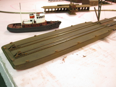
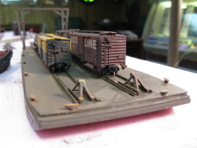

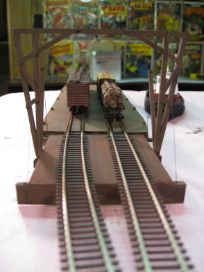
I'm awfully glad I decided to go ahead and plank over those ugly ties. It turned out to be a relatively easy task, and the end result is a much more convincing looking float.
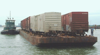
As on the log dump, the first thing I did was remove the tie ends. Then I simply cut variously shaped pieces of planking out of Evergreen "V-Groove" sheet styrene (.020" thick for the planks between the rails and .040" thick for the rest of the deck). For plank spacing, I went with .060". Then it was simply a matter of CA'ing the various sheets to the deck, followed up by paint (Roof Brown again), weatherwash and Bragdon. And once finished, I think I actually came pretty close to nailing the prototype:
The apron required that I finally gird my loins and enter the dreaded and mysterious land of scratchbuilding - something I haven't even attempted since I was like 10 years old (you know, tin cans and shoe boxes). And actually, this turned out to be a pretty simple and straightforward task (although admittedly, it's not like I was trying to build the Taj Mahal or anything). Basically I followed the plans as published in the layout book, fabricating all of the various pieces from Evergreen sheet styrene (V-Groove again) along with a couple of different flavors of Evergreen strip styrene. Once assembled, I painted everything Tamiya Red Brown, and then finished up with the usual coatings of weatherwash and Bragdon.
For the cabling, I simply Dremeled a few holes through the various timbers and then threaded lengths of BJ EZ-Line through them. With the line in place, I then filled in the holes on one end with WS Foam Tack Glue, pulled the lines tight, and then filled in the holes on the other end (you want to use white glue with EZ-Line - anything else tends to shrivel it).
And so, that's that, my first scratchbuilding job. Blimey, what's next? Handlaying track?! (Um, no)
01/23/08 - Adventures in wood
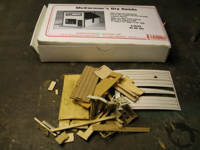
I finally figured out why I used to have so many problems with wood kits, and why (up until now) I hadn't run into any of those old problems putting together the buildings for this particular layout. Apparently the big secret with these things is to paint them before you assemble them. That's the procedure I serendipitously followed on my first three wooden kits, and all was well. But for whatever reason, I started assembling this one (AMB's "McCormac's Dry Goods") without first painting the parts. And holy carp, the pieces started warping like they were auditioning for a Picasso painting.
After fighting the warpage for a while, things got pretty ugly (as evidenced above). Eventually I just chucked the whole thing in the trash and started in on AMB's "General Service Building" kit. And after deciding my problem on McCormac's was not painting first, I went ahead and sprayed all of the pieces on this kit before getting glue anywhere near them. And sure enough, everything went smooth as silk. So, lesson learned. And I guess I'm lucky I learned it on a $12 kit instead of a $70 one.
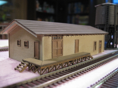
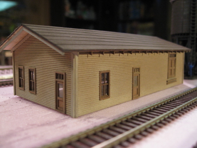
Since all of my buildings lately seem to have tended towards dark brown, I decided to lighten things up a bit on this one. For the walls, I used Floquil "Concrete" (sort of a yellow-brown). Then I went with Tamiya "Red Brown" for the doors, windows, trim and dock support. Lastly, Floquil "Rail Brown" for the dock itself and Floquil "Reefer Gray" for the roof.
So, I'm back on the horse. Now I just need to pick up another McCormac's and show it who's boss.
01/24/08 - In your face, McCormac's!
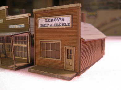
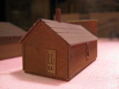
Yeah, uh huh, that's right. Who's your daddy now?!
OK, anyway... I painted this one Floquil Reefer Gray on the base and roof, Tamiya Red Brown on the walls, Floquil Concrete on the doors, windows, trim and boardwalk, and Floquil Tuscan on the chimney (Floquil Grimy Black on the top). Once assembled, I finished things off with a bit of Bragdon. And since I'll probably want to light this thing someday, I also drilled a big ol' hole in the base.
Already having a general store, I decided "dry goods" was going to be kind of redundant. So, seeing as how this is lake country, I went ahead and rebranded it as a bait and tackle outfit (once again creating the custom sign on my computer). And I don't know what the deal with the above picture is- that sign doesn't look nearly so neon white in real life.
I have one more wooden building I'd like to add to town, but for some stupid reason it's back-ordered at BLW. In the mean time, I guess it's time to get out the saw and start hacking away at all that foam.
01/29/08 - The base is built
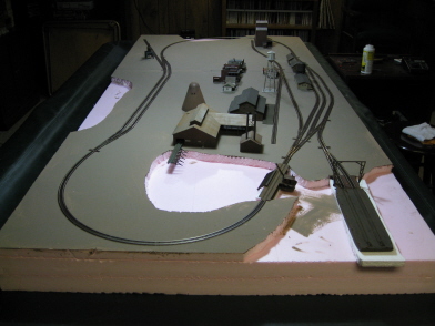
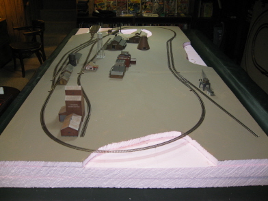
The first thing I did was take a big ol' saw to all three foam sheets, cutting off 6" worth of length and width. So, no going back now - the layout is 7.5' X 3.5' and that's that. And for a change, I actually left myself a decent amount of breathing room around the edges (rather than my usual modus operendi of running track literally right up to the edges and then lamenting it later on).
Next, I took a marker to the top sheet, plotted out the lakes and the gorge, and then cut out the pieces with a small saw. Once the dust settled, I glued the top sheet to the middle sheet (using WS Foam Tack Glue). While the glue was drying, I also went ahead and slapped on a coat of cheapie interior latex paint to get a jump on hiding all that pink bedrock.
Sawing this pink foam, though not nearly as messy as cutting the white beaded stuff, still produces a prodigious amount of fine, pink sawdust. I swear, you vacuum and you vacuum, and the crud is still all over the place - eventually finding it's way into every room in the house. So, rather than incurring further wrath from my wife, I decided to do my cutting on the bottom "frame" sheet using my WS "Hot Knife" instead of a saw (and yo - out in the garage, with the door open - the fumes from this stuff'll give ya Homer Simpson style brain damage otherwise). The hot knife generally yields less accurate results than does sawing. But in this case, I decided it wasn't particularly important that I worry about flat (or even straight) edges. And frankly, maintaining marital bliss seemed like a higher priority at the time.
I figured 5" wide for the edges and center supports was more than sufficient, so that's what I went with. I did go a little wider on the gorge end though, figuring I might want to have the option of digging my gorge right down into the frame later on (timber bridges being more dramatic with longer, y'know, timbers). Once I finished the cutting, I went ahead and glued the top two sheets to the frame.
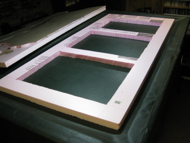
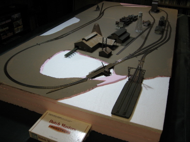
At this point I figured there was no way in hell I'd be able to fill in all those (eventual) lakes with a full inch of "water". So, I cut myself some sheets of 3/4" white foam and raised the lake beds up to more manageable levels. So, let's see - remove 1" and add back 3/4" - I guess that makes my lakes 1/4" deep now. And as luck would have it, this also raised my barge and apron up to the exact height they needed to be in order to hook up with the track on the top sheet (and yes, I put short mock-up sections of cork roadbed underneath the top sheet track, so no surprises later on - it all lines up perfectly).
Initially, I decided to connect the log pond to the "big" lake via a narrow channel (and plunk the log dump betwixt and between). However, once I actually got down to the business of putting things in place, it became obvious that that particular pig just wasn't going to fly - the whole configuration looked just plain weird. And aesthetics aside, the "reality based" problem was that there wasn't anything to stop logs from floating out of the pond and on out into the lake (and causing all sorts of subsequent calamities). So anyway, to make a long story short, I glued a short stretch of pink land back in, separating the log pond from the lake.
The log dump itself took a bit of finagling (vis'a'vis lining it up with the track on the top sheet). Plunking it atop a quarter inch piece of foam turned out to be too low, whereas a half inch piece placed it too high. So, digging deep into the kludge box, I tried a quarter inch piece of foam mounted atop some bits and pieces of cork roadbed (approximately 1/8" thick). And lo, that turned out to be just the right elevation - the rails on the dump lined right up with the rails on the top sheet (and no, I didn't forget to put some temporary roadbed underneath the top sheet rails this time either). So, with that particular piece of geowhizometry accomplished, I then finished things off by filling in the various dead spaces with bits and pieces of 3/4" foam (to minimize the future "fill it all in with water" factor).
So, that all turned out pretty well. My only concern now is all that (eventual) water under and around the dump - and just how in hell I'm going to manage painting it. I mean, I'm going to have to somehow paint all that water blue (and at the same time not paint the log dump supports blue), and all in very cramped quarters. Yikes! Fortunately, that's a problem for "Future Mark" to worry about. On the other hand, "Today Mark" is going to pour himself a drink and congratulate himself on another blog entry well and truly finished. Cheers!
02/03/08 - Some stuff I won't be using...
I'm about ready to start gluing down my track, so I decided to once again revisit what's out there vis'a'vis uncoupling widgets and turnout throwing whozamawhatsits.
Now, as far as actual layout operations are concerned, well, I don't do much of that kind of thing myself (still being content to simply run my trains around in circles). However, I've always been fascinated by the idea of automated uncoupling (and yeah, I've even dabbled with it in the past). So, I generally install Micro-Trains uncoupling magnets on my layouts on the off chance that I might come down with the operations bug some day.
As for the actual magnets, I've never been real happy with the two flavors offered by Micro-Trains. The "between the rails" ones are too ugly to be tolerated (especially now that I've gone C55). And the "under the rails" ones are too big and bulky and, in general, just kind of a pain in the ass to install. So, after a bit of searching around, I discovered what looks to be (to me, anyway) the perfect operations magnet - S&L Enterprises' "Totally Hidden Uncoupler"-
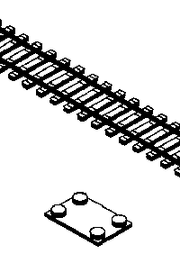
Basically you get a thin piece of sheet metal and four "rare earth" magnets (very small and very powerful). To set it up, you simply arrange the magnets on the plate (one on each corner - with two on one end polarized one way, and the other two on the other end flipped the other way) and voila, instant magnetic uncoupler. Arranging the magnets "just so" (in order to get the best possible performance) takes a bit of trial and error, but ultimately it's pretty simple. I found that placing them so that they are more outside the rails than in works best. Best of all, the entire rig is exactly the same thickness as traditional cork roadbed. So, simply leave yourself an appropriately sized gap in the roadbed, stick in the uncoupler assembly and then ballast right over it. It's actually quite slick.
So, yeah, I picked up a few of these, experimented around with them to make sure they were going to work, and then... changed my mind on the whole deal. What can I say? Yes, I've always thought that automatic uncoupling via magnets was, in theory, a pretty cool thing. However, I also started recalling some of my past experiences using automatic couplers and suddenly came to my senses. Basically what I remembered was a lot of frustration and a lot of trips back and forth between my layout and my workbench in order to fiddle around with balky couplers (trip pin too long, trip pin too short, trip pin pointing the wrong direction, coupler box too sticky, etc, etc, etc). Ultimately, I decided to stop kidding myself - I'm just never going to use these things. I don't need the aggravation. And anyway, I guess I can always go with a simple "Rix Pick" should I ever decide to "operate" my layout.

Still, if you're thinking of going the magnet route yourself, I do recommend these S&L magnets. They're very cool.
So, with the magnets vetoed, I turned my attention to groundthrows. Now, I've been using Caboose Industries groundthrows on my past few layouts, and in general I've been pretty happy with them. However, I've also always wished they were a little smaller (being basically 8 N scale feet tall with the lever pointing straight up). So, I decided to scrounge around a bit and see if there wasn't something new and interesting out there to try. And sure enough, there was. Namely, this Micron Art "Archimedan Ground Throw"-

Pretty nifty looking, eh? I especially like the realistic looking little flag that you rotate with your fingers in order to slide the turnout throwbar one way or the other (note - the cover is not installed in the above picture - you don't actually see the gears when it's all put together).
So, thus intrigued, I decided to order a two-pack just to see how workable they might be. And mighty glad I am that I didn't go ahead and order more than that, because this is what I got in the mail:

Now, I don't know if you literally need to be Archimedes himself in order to assemble one of these diabolical little units, but it certainly couldn't hurt. I took one look at all of those tiny little brass parts and broke out into a cold sweat when I started estimating what it might take to assemble eleven of them (and actually get them all to work). Suffice it to say, I decided to leave the Archimedean ground throws to the rocket surgeons and went slinking back to Caboose.
Meanwhile, over at the Caboose website, I discovered that Caboose has actually come out with a groundthrow (224S) specifically designed for Atlas Code-55 turnouts-
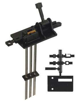
So, I picked up one of these to see what they're all about. And damn if the cold sweat didn't start up yet again. It turns out that Atlas has provided contacts on their C55 turnouts for (should you so desire) powering the frogs. And these new groundthrows provide contacts such that power gets routed correctly to the frog (depending on which way the turnout is thrown).
Now, that all sounds good in theory. However, it's also a whole lot of extra wiring. Basically you need power leads for every single throw/turnout. And with eleven turnouts to set up, that's simply more wiring than I'm interested in tackling. For a layout this size I'd originally figured on six, maybe seven sets of track power leads, tops. Frankly, I find wiring pretty tedious (who doesn't?), and addressing a problem that I don't actually have (small locomotives stalling out on non-powered frogs) seemed like a pretty big waste of time and effort.
I guess the final nail in the 224S coffin is the complexity of the groundthrow itself. Caboose groundthrows are, in general, pretty reliable. However, I've also had to replace more than a few of them that (for one reason or other) flaked out on me. And the thought of having to replace one that has a bunch of wires connected to it was definitely not giving me a case of the warm fuzzies. IE, so much for the 224S's. I guess I'll just stick with Cabooses's traditional N scale groundthrows and leave it at that.
02/05/08 - Then again...
Well, never let it be said that when Spookshow Nation speaks, I'm not willing to listen. The groundswell of support for the 224S's has been overwhelming, so I guess I'm just going to have bite the bullet and go ahead and give 'em a try. I'm still not thrilled about all the additional wiring, but I guess the added benefit of actually being able to run the tiniest of locos might just justify the effort (yo Atlas 2-6-0, I'm talking to you).
And once again, thanks for all the feedback. It's much appreciated.
02/05/08 - Tidied up the lakebeds and got the roadbed and track glued down
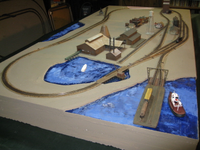
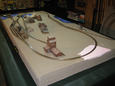
I started off the festivities by applying WS plaster cloth to all the gaps between my 3/4" lakebed inserts and the top foam sheet (basically creating shorelines in the process).
For the log dump, I decided to go ahead and paint the base blue before gluing it into place in the log pond. I figured this might help me out later on when I have to paint the eventual pond water under and around the dump - IE, the blue paint underneath the surface of the water should (hopefully) conceal any spots I miss while painting the surface. Well anyway, that's the theory. We'll see what happens a few months from now when I actually get to pouring the pond water...
Speaking of pond water, I did go ahead and fill in the trenches around the dump with WS "Realistic Water". Given how long it takes even thin layers of RW to set up, I figured I might as well go ahead and get a head start on this particular area (what with the water being a half inch deep or more in spots). And as expected, the RW did go a bit cloudy on me (it being best limited to thicknesses of a millimeter or two as most). However, the blue underneath the surface wound up showing through quite well, so that's good news.
Once I finished all of that business, I went ahead and painted the rest of the lakebeds blue. No, not really necessary since I'll ultimately be painting the (eventual) lake water blue. But, that won't be some for some months, and in the meantime I'd rather have blue lakes (as opposed to white ones). In other words, yeah, just me being anal retentive again.
I followed the same basic procedures for gluing down the roadbed and track as documented on my previous layout blogs, so no surprises there. And as expected, once I got down to gluing the track in place, I did wind up having to replace a couple of pieces of track that no longer worked (and yes, I even had to custom cut a couple of curves - but, oh well, no biggie).
Once again, I went with Midwest Products cork roadbed (pretty much the only game in town when it comes to cork - my preferred roadbed). And my ongoing pet peeve with MP's roadbed is the fact that only one side has a decently beveled edge. Now, I've been told that the solution (or at least a solution) is to sand down the edges on the icky side. And so, deciding I wasn't going to live with half crappy roadbed on yet another layout, I went ahead and gave sanding a try. And OK, sure, I guess it does work. But unfortunately, it's also a very tedious and time consuming procedure. And after a few minutes of that nonsense, I said screw it and decided to just toss the crappy halves and only use the good halves. Yeah, this basically doubled my roadbed expenses, but hell, the stuff is cheap and my layout is small. Frankly, I'd rather pony up the extra saw buck than waste my time sanding miles of cork...
I decided to go with seven sets of track feeders, scattered hither and thither (the Atlas C55 ones with the built-in joiners). So, I guess my next task is to get them wired up to power and then see about playing with some trains! I tell ya, that sounds like a lot more fun than continuing my Timber Trestle slog (but that's a story for another day).
02/08/08 - Frustration and stupidity - The Bridge O' Death Saga
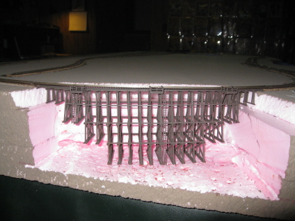
Over the years I've assembled numerous "Cornerstone" structure kits - in fact, damned near every one ever made. And for the most part, I've generally been pretty impressed with how easily they go together. Ah, but that was before I'd met The Bridge O' Death (aka "Timber Trestle"). Good God, talk about your exercise in frustration! What I thought might take a day or two to build wound up taking me a week (a week punctuated by much hair-pulling and teeth-gnashing, mind you).
The basic problem with this kit is that pieces are all in desperate need of just a whole lot of slots and tabs - or at least something to let you know that you've glued a piece exactly where it needs to go, thus allowing you to move on to the next piece with some degree of confidence. I lost track of the number of times I had to glue, tear off and then re-glue those stupid verticle supports ("bents", I believe you call them). You get one of them slightly misaligned relative to the rest and then suddenly none of the horizontal supports will glue into place properly. Or worse still, you muddle along, taking your best guess at how things are supposed to fit together, and suddenly you notice that half the pieces are all crooked and basically pointing every which way. And so, unless you want your bridge to look like it was built by a team of chimps, you pull it all apart and start over again. Blah!
Adding to the frustration is the fact that, as you plod along gluing pieces together, you never quite feel like things are going to hold together firmly while the glue dries. Basically, the whole project feels like an exercise in plate spinning. You glue on a piece, move on to the next piece, and the next piece, and the next piece, trying to get to a point where the stuff will hold together by itself (rather than having to constantly go back and readjust things yourself). And since everything is connected together in one vast spiderweb, fiddling around trying to align one piece inevitably screws up five other pieces that you'd thought you'd finished with ten minutes before. I tell ya, the whole damned thing is just a giant house of cards waiting to come tumbling down in one giant mass of plastic and half-dried glue.
Now, this kit is actually designed such that it can be built a number of different ways - either straight, curving (20" radius), or a combination of the two. And I dunno, my guess is that it's probably easier to build the straight version - which leads me to believe that it's this very flexibility (vis'a'vis the parts) that accounts for the difficulty and lack of precision when it comes to getting the pieces put together. Or maybe not. Maybe it just sucks.
So, yeah, there's all of that. But get this - I actually decided (of my own free will) to go ahead and make this already difficult task even more tedious and time-consuming than it was to begin with. How, you ask? Well, here's the thing. Over the years I've always lamented the fact that plastic "wood" buildings rarely look "woody" enough to me. And what it usually boils down to is the fact that the parts are all generally flat, featureless, and utterly lacking in any sort of wood grain. And once painted, they simply wind up looking too smooth, too shiney and too plastic-y. So, I figured that since I was going to go to all the trouble of building a complicated wooden bridge, I'd also make damned sure that it actually wound up looking like wood when I'd finished. So, yep, you guessed it. Prior to assembly, I went ahead and sanded every single part. Wow, total insanity! However, truth be told, I do believe all of that effort actually paid off - it really did wind up looking awfully nice.
So, that's the frustration part. Now, comes the stupidity part. As you can see from the picture above, I dutifully built this thing damned near as tall as possible. The bents come in six different lengths, and I used all but the longest ones. And boy oh boy, did it ever look cool once I'd (finally) finished it.
Once assembled, my next task was to remove a bunch of foam. So, I attacked my layout with the ol' WS hot knife in order to create a big ol' gorge for my creation to span. Then, quivering with anticipation, I plunked it into place, and... (drumroll) came to the startling realization that it looked completely out of place on my layout! Oh, the horror! The horror!
I mean, what was I thinking? This layout is lake and timber country, so just how in the hell could a gorge that deep possibly exist so close to so many lakes? I mean, obviously it would be filled in with water and be, y'know, a lake! Water tables are water tables, and there's just no getting around that.
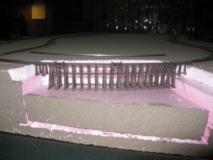
So, much to my chagrin, I started lopping legs off my beautiful bridge. Agonizing yes, but it had to be done. My whole layout would've looked competely stoopid had I left it the way it was. And although the redesigned gorge is still relatively deep, I think I can get away with it if I put a lake at the bottom and then landscape the sides and surrounding terrain convincingly enough. Anyway, we shall see...
02/10/08 - Cut some logs for the log pond
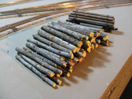
Wow. Middle of February in Minnesota, temperatures well below zero, snow blowing around in howling winds... and I'm out there in my back yard trimming the lilac bushes. It's a wonder my neighbors didn't call the guys with the butterfly nets.
02/10/08 - Meanwhile, back at The Bridge O' Death
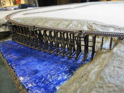
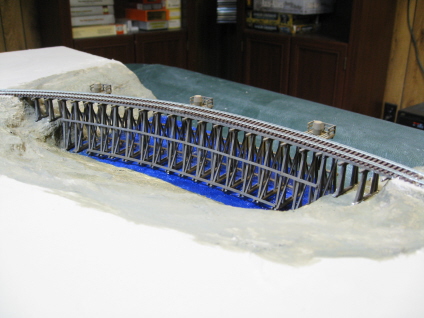
OK, now we're getting someplace. This new water-filled depression doesn't look nearly as crazy as my original "grand canyon" did. And I think once I get some hills and whatnot built up on top of the layout, everything will work out just fine. Water table? What's a water table?
In order to debigulate the gorge, I started by gluing a huge hunk of the original foam back into place. However, once I'd done that, I didn't really feel like messing around trying to cut a lot of precise little pieces of foam in order to finish off the sides and the floor of the new gorge/lakebed. What I really needed was something like modeling clay. So, I hied myself down to YOLHS to see what my options might be.
The first thing I came across was Woodland Scenics "Mold-A-Scene Plaster". And shoot, right there on the front of the box it proclaimed "Shapes like clay, can be carved, fills gaps and holes". Well, gee, that sounded exactly like what I was after. So, I bought a box. Unfortunately, I can't really say that it worked as advertised. I don't know what (if anything) I did wrong, but what I wound up with wasn't anything like clay. Basically I got a big crumbly mess that couldn't be shaped, molded, carved or anything else. Still, not having any other ready options, I went ahead and used it to fill in all the gaps, and then did my best to make a flat lakebed out of it. After that, I decided to switch back to "old reliable" (plaster cloth and foam) in order to finish things off.
So, that's that. And as much as I would've liked to have kept the original bridge/gorge, I think ultimately this looks much better (at least on this particular layout).
02/11/08 - Finished wiring up the main track power leads
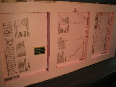
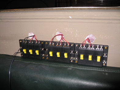
I glued three Atlas "Connector" boxes to the front of the layout and then ran wiring to all of the terminal joiner leads I'd installed previously. Then, I ran a couple of wires from the first connector box to my power station (the same old rolling podium I've been using for years) and ran my little Shay around in circles for a while. No problems, so I guess everything worked.
For the spots where the wires wound up coming down through the edges and/or cross-supports of the frame layer, I simply used my WS hot knife to cut out channels for said wiring to traverse. Otherwise, the wires would wind up sandwiched between the frame and the tabletop, and well, that can't be a good thing, can it?
My next task is going to be wiring up all of those 224S groundthrows. And since I don't really want to add a bunch more connector boxes, I installed a Miniatronics "PDB-1" underneath the layout instead. This is a nifty little unit that has 1 pair of lugs in and 12 pairs of lugs out. And, in a minor nod to safety, I screwed it to a block of wood and then glued the wood to the foam (as opposed to gluing the PDB directly to the foam). I don't know how necessary this is, but it helps me sleep at night. To help minimize the wiring later on, I glued the PDB directly underneath the largest comglomoration of turnouts (over on the south end of the yard, towards the car float). Lastly, I wired it to the Connector box array.
Now, I'm not big fan of wiring. In fact, I kind of hate it. It's especially tedious on these tabletop layouts, where getting at the underside is generally a big pain in the posterior. Which is why I was muchly delighted when I discovered that this layout is narrow enough, light enough, and thick enough that I can flip it right up on its side and have it stay there - thus allowing me easy access to the underside. I'll tell ya, that's going to come in might handy as I slog through the process of getting all those frogs wired up.
02/11/08 - Finished Blair Line's "General Store" kit
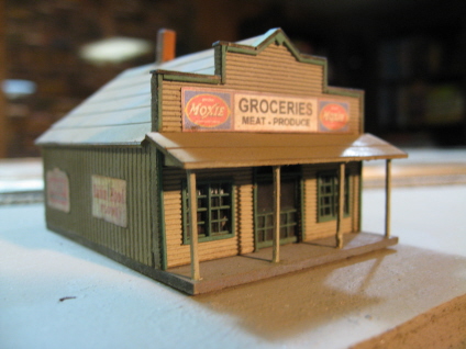
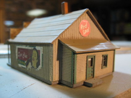
This is my first Blair Line laser-cut wood kit, and overall I'm pretty pleased with it. The pieces are basically the exact same deal as the AMB wood kits, so I didn't have any great difficulty getting things put together. I did run into a couple of minor issues, though. Right out of the box, the two side walls were a bit warped. Also, the stick-um on the roofing material was pretty pathetic. Ultimately, no big deal though. Blair's walls are a bit thicker than AMB's, so I managed to de-warp them without snapping them. And a bit of well-aimed glue took care of the non-sticking shingles.
Color-wise, I went with Floquil "Reefer Gray" spray paint for the foundation, "Concrete" for the walls, honest-to-gosh "Roof Brown" for the roof, and "Dark Green" for the windows, doors and trim. For the chimney, I brushed on Model Master "Rust" for the sides and Floquil "Grimy Black" for the top. I really wanted to paint the walls white - I mean, they just cry out for it. Unfortunately, me and white have had our problems (what with the runniness and all). And ultimately, I just didn't feel like risking a major screw-up. Yup, another "mediocre modeler" compromise.
This kit comes with one lone decal (printed on some sort of cheapie ink-jet printer, or so I'm assuming), as well as a cardstock sheet featuring various "Good Ol' Days" signage. I was pretty unimpressed with the decal, as it basically fell apart on me as I tried to install it. Fortunately, advertising signage on the sides of old buildings almost always looks better when it's a bit beat up, so no big deal there. I was a bit happier with the cardstock signs, and made liberal use of them. I especially like the assortment of "front" signs - very cool.
Since Slackjaw already sports one "General Store", I decided to make this one an out-and-out grocery store (figuring that having the two wouldn't be entirely redundant). Overall, I really like the look of this building, and I think it's going to fit in very nicely next to the gas station. I particularly like the window inserts (and especially the "screen door" insert for the front doors) - luxuries not offered with AMB's kits. OK, no one is ever going to see them (let alone appreciate them), but I know they're there, and that's enough. Those satisfactions are permanent (yo - name that obscure movie quote).
So anyway, that should pretty much do it for Slackjaw. In fact, it damn near does it for buildings in general. I plan on building a cabin for the western lake, but that's about it (or at least as "it" as it ever gets with me).
02/17/08 - Finished installing the 224S groundthrows
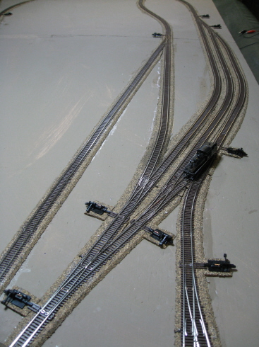
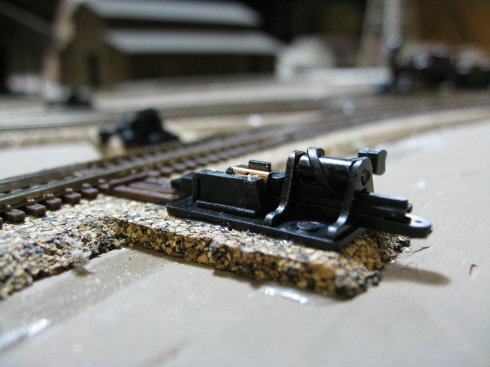
As I suspected, it took me the better part of a week to get all eleven of these babies installed. Not that installation is particularly difficult, but I do tend to get burned out pretty quickly on this kind of stuff. I can stand doing maybe one or two on any given day, but that's about it.
Anyway, before I get on with the blow-by-blow, let's spend a minute or two talking about frogs and what it means to power one. A turnout's "frog" is the section in the middle where the two pairs of divergant (IE, oppositely polarized) rails all come together. Most turnouts deal with this obvious short-circuit situation by employing a plastic frog. IE, the metal rails give way to plastic before they meet, thus avoiding the short-circuit. The major downside to the plastic frog solution is that locomotives with limited pickup have a tendancy to stall out when one or or more of their current-conducting wheels land on the non-powered frog. Conversely, more advanced turnouts have current-conducting (IE, metal) frogs, where the polarity of the current in the frog is determined by which way the turnout is thrown. A short-circuit is still possible, but only if a locomotive enters the "Y" end of the turnout from the non-thrown direction (IE, not only will it cause a short, but it'll also derail).
I have to say, I found the wiring instructions for these particular groundthrows to be a bit confusing (at least as far as Atlas code-55 turnouts are concerned). They show a lot of extra track power leads and insulating joiners and whatnot (none of which you really need to worry about). The turnouts have built-in gaps off the frogs, and track power flows in from the adjoining rails without any additional assistance. So the task here basically boils down to providing one set of track power leads into the groundthrow contacts, and then one power lead out of the groundthrow and into the frog power contact on the turnout (look for the tiny little metal loop outside the ties, up by the frog). The groundthrow itself routes the correct polarity to the frog (based on which way the turnout is thrown).
The first task is to pick which side you want to install a given groundthrow on, and then trim the slidebar on the opposite side of the turnout. I don't know exactly how much of said slidebar it's safe to remove, but I basically just clip off everything outside the little plastic piece that runs parallel to the rails. Next, I glue down some cork roadbed on which to mount the groundthrow (the supplied "shim" not being thick enough to raise the groundthrow up to the height of the turnout slidebar). And to make sure the little prong in the groundthrow slidebar (that hooks into the turnout's slidebar) has room to move, I also go ahead and carve a small chunk out of the cork underneath the end of the turnout slidebar. Next, I drill a big hole through the cork for the metal contacts that mount under the groundthrow, and then use my "coat hanger rod" tool to punch a skinny hole through the foam over by the frog contact.
Now, it gets fun. I next tape the end of a length of very skinny wire (the skinniest I can find) to my hanger rod, and then jam the wire down through the hole over by the frog contact (hopefully getting all the way through to the underside of the layout). Next, I pull the rod all the way through the layout and then push it back up through the hole underneath the groundthrow, and then detach the wire from the poker (leaving lots of slack to work with on either end). Next, I tape the end of a length of two-conductor wire to the rod and push that up through the hole under the groundthrow. Given the thickness of my layout's base, I have to do all my soldering on top of the layout - hence, this seemingly odd procedure.
The next task is to assemble the groundthrow. The instructions are initially a bit mind-wobbling, but I eventually figured things out- first, stick the skinny side of the copper contact into the groundthrow "pocket". Then, fix it in place with one of the provided black plastic bits (flat side butted up to the copper contact). Next, stick the 3-contact thingy in place. Lastly, stick the claw/prong end of the groundthrow on. For these, I used the two-prong piece (cutting off the outer prong). That's it, the rest of the stuff I chuck. It'd be nice if you could install the "prong" end-piece pointing up instead of pointing down (which would allow the groundthrow itself to be placed lower relative to the track). Unfortunately, it only seems to go on the one way.
Once the groundthrow has been assembled, I then solder the two-conductor wire to the outer two contact "legs" and the skinny "frog wire" to the center leg. Then I pull all that wiring back under the layout until all the slack is out and the groundthrow is sitting on the cork base. Next, I pull the slack out of the skinny wire (from the top), nip off all but a couple of inches and then solder the end to the frog contact. Once soldered, I pull any remaining slack back under the layout. Then it's just a matter of connecting the two-conductor wire to track power (IE, the PDB) and then testing out the groundthrow to make sure the polarity is right. If not, I switch the wires on the PDB and then try again. Once everything looks like it's working, I apply a bit of FTG to the bottom of the groundthrow, and then hold it in place with a couple of skinny brads (through the two holes provided in the base of the throw).
And so? Well, first off, they're big, they're black, and lord, they are ugly. And I don't know what (if anything) I'm going to be able to do to conceal (or at least minimize) all that ugliness. I'd love to spray 'em with some Grimy Black to kill the shine, but I've long since learned my lesson vis'a'vis applying any sort of chemical spew to these things. IE, unless you want them to gum up and stop working, it's best to keep anything remotely sticky away from the moving parts... So, at this point I'm open to suggestions (hey, you guys talked me into using these things, don't abandon me now).
So, form being not so great, how about function? Well, I've never used turnouts with powered frogs before, and I have to say, I'm awfully impressed by the results. I can creep my Atlas 2-6-0 (pretty much the tiniest locomotive I own) around the entire layout at ridiculously low speeds, and without a single stall. So, defintely a big thumbs up there. Now if I can just figure out a way to de-uglify them a bit...
02/18/08 - Another C55 glitch
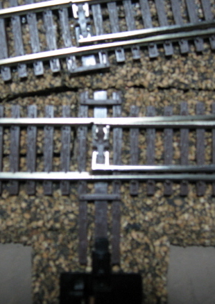
With groundthrows now firmly in place, I finally got to do some serious roundy-rounding last night. And during the course of said running, I discovered another problem with Atlas's Code-55 track - specifically, with the turnouts. I was hauling a little passenger train around with my Atlas 2-6-0 and was muchly annoyed to find that the Mogul's pilot truck would consistantly hop the rails about every 15 minutes or so. I spent a while checking and rechecking the gauge on the locomotive's wheels, but that didn't get me anywhere - they were spot on. IE, the problem had to be in the track someplace.
So, I throttled up the loco and waited for it to derail. And after much observation, I eventually identified one of my turnouts as the source of the problem. As the Mogul went through said turnout, one of its drivers would ride up off the rails, lifting up the front end of the locomotive just enough to derail the pilot wheels. At first I thought maybe my sprung groundthrows (which apply pressure on the slidebar) might be screwing up the track gauge at the points. However, after measuring the gauge and finding it correct, I discarded that theory.
Next, I spent just a whole hell of a lot of time slowly pushing the locomotive backwards and forwards over the slidebar and watching the wheels. And what I finally noticed was that the wheels on one side were hitting the little piece of plastic that connects the points to the slidebar. Apparently there's just enough slop in those slidebar pieces to allow that center piece of plastic to ride up slightly higher than the ties, and consequently interfere with a locomotive's wheels. After experimenting with a few other locomotives, I eventually figured out that the problem is pretty minor and only seems to affect steam locomotives with light pilot tracks - diesels and larger steamers glide through with a bit of a clunk, but they don't derail.
To fix the problem, I fired up my soldering iron and carefully melted the offending end of the center plastic piece such that it no longer stuck up higher than the surrounding ties. A pretty terrifying experiment for sure, as I had nightmarish visions of destroying the turnout and then having to tear up miles of track in order to replace it. Fortunately, this actually worked quite nicely and I was subsequently able to run my little Mogul around the mainline for several hours without further incident. I then checked out all the rest of my turnouts and found one more that had the same problem. However, a quick zap with the soldering iron took care of that and now everything seems to be working fine.
02/20/08 - Fixed some gaps in the ties
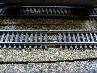
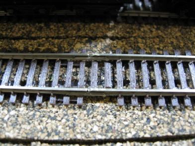
Whenever I need to custom-cut a section of track, I always wind up with gaps in the ties (mainly 'cuz I still prefer to use joiners on my track, as opposed to solder). Said gaps are pretty ugly looking, but for whatever reason they've never really bothered me - up until now, that is. I guess the C55 track is nice enough looking that little problems tend to stand out a lot more. Anyway, whatever the case, I went ahead and cut myself some ties and glued them to the roadbed in the three spots where I had custom track gaps. And no, I'm not going to bother adding tie ends too - I mean, come on. I may be obsessive, but I'm not nuts...
02/20/08 - Settled on a street plan for Slackjaw
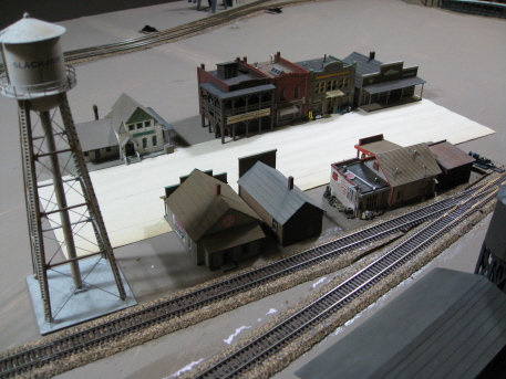
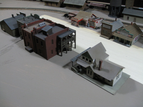
I decided that before I got started gluing down foam for the various hills and valleys outside of town, I'd better settle on an actual plan for the town itself. I sure don't want to get all that foam glued in place and then discover I didn't leave enough room for streets, sidewalks, alleys and whatnot.
For the main drag, I decided on an overall width of 5 inches (figuring this would provide plenty of room for traffic lanes, parking lanes and sidewalks). Next, I cut myself a sheet of a 5" wide paper - a nice visual aid for the simple minded (IE, me). Next, I drew a line down the center and then placed a couple of vehicles on the paper, side-by-side (IE traffic lane and parking lane). That left about three-quarters of an inch on either side for sidewalks, which seemed about right. So, I stuck the paper in place on the layout and then arranged the buildings (letting aesthetics be my guide, but with a slight nod towards logic as well - IE, the buildings with loading docks went on the side of the street where I have room for an alley).
I have to say, I think this all turned out really well. The buildings I picked work together very nicely, and overall the whole thing does look like a fairly realistic "really small town".
03/03/08 - Added some pilings to the carfloat landing
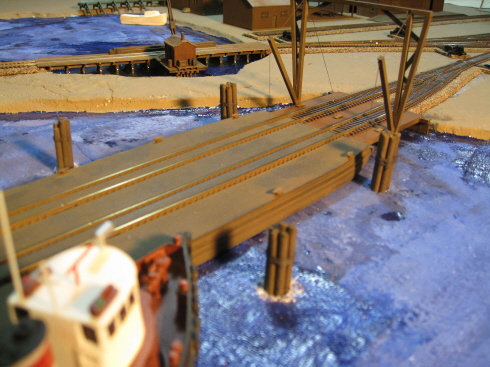
I'm not exactly Captain Nautical over here, but my understanding is that these things are used to guide ferries, barges, etc into their landings. The Kootenay plan doesn't mention them specifically, but they are pictured in the article. So, what the heck, I decided to go ahead and add some.
Calling this a scratchbuilding project is probably a bit more grandiose a description than it deserves. But hey, if it sounds more impressive that way, I'll take it. Materially speaking, I went with a couple of different diameters of wooden dowel. The first thing I did was roughly sand them (for that simulated woodgrain look) and then cut them into a bunch of 2" sections. For each individual bundle, I picked a random number of individual "logs" (five, six or seven- just for some variety), slatherered them with some wood glue, and then bundled 'em up (held together with a rubber band while the glue dried). I used my fingers to wipe off most of the excess glue, with the leftover lumpy shmoo serendipitously making the dowels look less like dowels and more like logs. Once the glue dried, I removed the rubber bands and then sprayed the pilings with Floquil Roof Brown. For the "cabling" (that ostensibly holds the bundles together), I went with EZ-Line - basically just wrapping it around a few times, tying it off, and then dabbing on a bit of FTG to fix the loose ends in place.
So, there ya go, a simple little 30 minute project.
03/03/08 - Finished New Rail Models' "A-Frame Cabin" kit
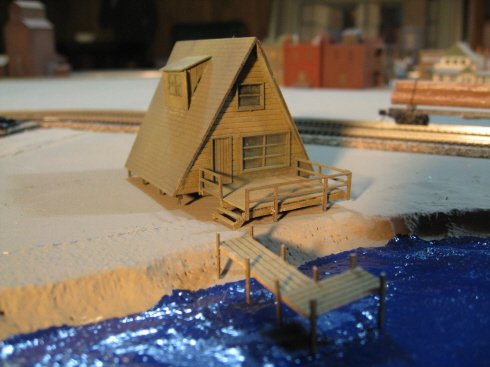
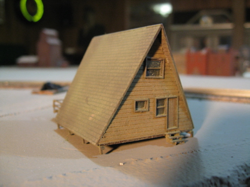
This is my first "New Rail Models" kit, and overall it's pretty much the same deal as an AMB kit - IE, laser cut wood walls, floors, roof, etc, and then peel-n-stick shingles, doors, windows, trim, etc. Having said that, I'd say NRM's quality is not quite up to AMB's standards. I found a lot of the pieces to be a bit warpy and/or flimsy (having oops-snapped more than a few in the process of putting this thing together). And the whole assembly process was quite frustrating at times, particularly on the deck (what with all the damned handrails). No, not the worst kit I've yet encountered, but I won't be sending any Xmas cards to NRM either...
For colors, I went with Floquil Rail Brown for the deck and walls, and Roof Brown for everything else. And since I didn't really like the white-ish peel-n-stick shingles, I went ahead and re-colored them with Bragdon powder (first black, then green). Unfortunately, they don't really look very green in my pictures, so you'll just have to take my word for it. My camera doesn't seem to like the lighting in my basement at the moment...
I built the little dock out of leftover pieces. And now that I look at it, I think I'm going to have to add some old tires to a couple of those posts once I get to the detailing stage of things.
03/03/08 - Finished American Model Builders' "Interlocking Tower" kit
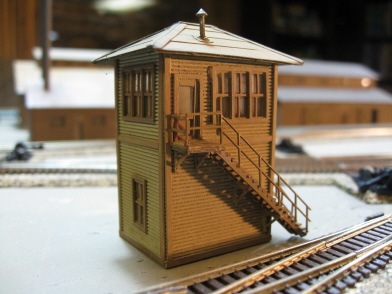

I don't know that a small yard like this one would necessarily have an interlocking tower, but who cares? I like 'em, so I added one. Better still, the more buildings I add now, the less generic scenery (yuck) I'll have to worry about later on. So, it's all good.
The kit itself went together pretty smoothly, although I did have a bit of a chuckle at the instructions (which assured me that putting together the stairs would not be a tedious task - oh yes it was). For paint, I went with the same color scheme I used on the "general service building" (IE Floquil Concrete for walls, Floquil Roof Brown for the roof, and Tamiya Red/Brown for everything else). I finished things off with the usual Bragdon treatment.
Looking at the pictures now, I'm wondering why I didn't go ahead and install some window shades in there. Damn, I might just have to pull the roof off and address that particular oversight later on... I guess I get so compartmentalized in my layout building "stages" (base, track, buildings, scenery, detailing), I sometimes forget that detailing can be an ongoing process...
Anyway, at this point there's just one more structure that I think I need to add to the mix - namely, a bit of housing. For some reason, we model railroaders tend to design layouts (towns and all) that fail to provide much in the way of places for actual human type beings to live. Trains, business and industry - all well and good, and great grist for the layout mill. But, presumably actual people run those trains and work at those industries. And, as such, I guess they should also be ceded the luxury of actually having someplace to live (hell, fair's fair). Unfortunately, the Kootenay plan doesn't provide much room for a whole lot of housing. So, I guess a judiciously placed mobile home is going to have to provide adequate living quarters for the entire population of Slackjaw... sorry guys!
03/10/08 - A slight diversion
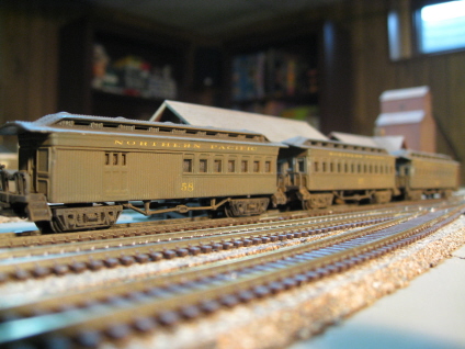
Sorry, I've been slacking off on Shay Stadium lately. Instead, I spent the past week working on this old-timey Northern Pacific passenger train for my 2-6-0 to pull around. Kind of a fun change of pace, though - and my first attempt at customizing some rolling stock.
03/10/08 - Rethinking my town plans
When it comes to city streets and sidewalks, I've always been a big fan of Woodland Scenics' "Road System". However, as I started contemplating putting down the plaster for Slackjaw, I ran into a bit of a snag. Namely, what to do about all of those buildings that already have built-in wooden boardwalks? Initially, I figured I could either just plunk them down right on top of the sidewalk layer (which would probably look pretty stupid), or go with wooden boardwalks for all the rest of the buildings (in lieu of concrete sidewalks). However, if I went the boardwalk route, I also figured I'd probably have to go with some sort of gravel road through town (just to match up the eras). And since I've never even seen a town that didn't have paved streets, I wasn't sanguine about my ability to dream up a realistic implementation for the latter option.
However, after a bit of research, I think I came up with a decent compromise - namely, building the boardwalks right into the sidewalk layer. Vis-
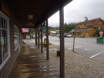
Now, I imagine trying to get my boardwalks nestled into the concrete (and without getting plaster all over them in the process) is going to be a bit of challenge. Still, I think it's worth trying - I really do like the look. And now that I think about it, I should probably also go with a "pull in headfirst" parking scheme for Slackjaw (as opposed to parallel parking). It'll eat up a bit more space, but it does seem to be the norm for really small towns.
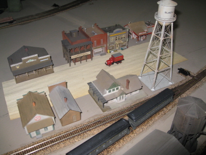
Somewhere during all this cogitation, I also decided that my gas station needed a bit more breathing room. So, I moved it over to the other side of the street (and consequently, rearranged some of the other buildings in the process). Hopefully this will be the final plan.
I'd prefer to put off getting started on the roads until I have the last building (the mobile home) in place. And I don't want to get started on the hills and stuff until the roads are in place. So... I guess maybe I'll take a whack at painting the ties and rails in the meantime.
03/19/08 - Track painting and groundthrow camoflaging
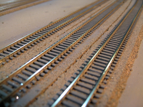
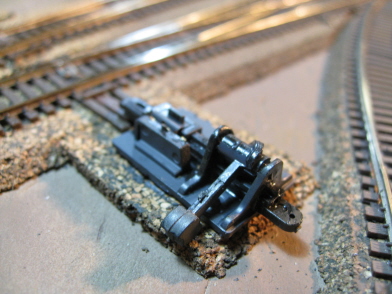
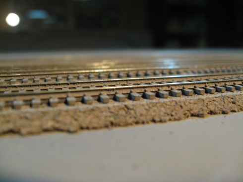
As nice looking as Atlas's C55 track is, out of the package the ties still look way too shiney and plastic-y to me. So, I decided to go ahead and hit them with a coating of Floquil "Roof Brown" spraypaint. And to insure that I didn't screw up my turnouts and groundthrows in the process, I went ahead and completely masked them off prior to spewing any paint. After the paint dried, I removed the masking tape and then carefully handbrushed all the ties in and around the turnouts. And as you can see, I think the end-result is some much more realistic looking ties. Better still, all of those ugly rail joiners basically vanished in the process.
On a roll, I decided to also take a whack at de-uglifying my groundthrows a bit. And, I dunno, I guess I'd have to call the results mixed (at best). Basically I brushed Floquil Grimy Black everywhere it seemed safe to brush it (without gooing up the works). Unfortunately, a lot of shiny bits remained and I still managed to render a bunch of the groundthrows immovable in the process (a problem I was eventually able to fix by applying a bit of Conductalube to the moving parts). I did manage to completely camoflage all of the shiny brass contacts though, so I guess I at least achieved that one small measure of success. Maybe when I get to the ballasting stage I'll be able to further conceal the bases by burying them underneath ballast and turf. We'll see.
So, now to see about painting the rails...
03/21/08 - Scratchbuilt (well, pretty much) a tug for my log pond
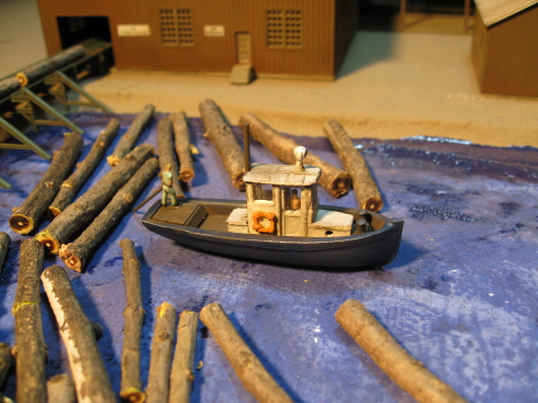
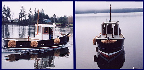
I've always had it in the back of my mind that my log pond needed some sort of boat (hey, those logs aren't going to get across the pond and onto the conveyor by themselves). However, I also thought that just sticking some dude out there in a canoe (or whatever) was going to look kind of boring. So... I spent just one hell of a long time scanning the web for something appropriate. Unfortunately, most of the really cool looking logging boats (like those used for towing log "booms" from place to place) were way too big for log pond duty. EG:
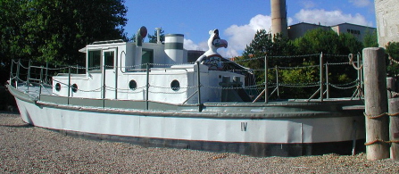
On the other hand, all of the actual log pond type boats I came across were, quite frankly, kind of dorky looking. EG:
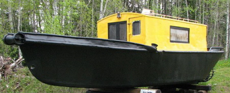
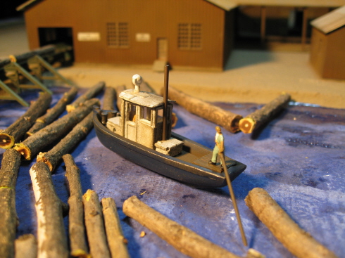
Fortunately, I eventually lit upon some pictures of this cute little tug - "The Godzilla". At 20 feet long (at most), it looked to be just the right size for my needs. And although I can't categorically prove that a boat like this was ever actually used at a saw mill, there's certainly no way to prove that one wasn't either. So, having already dipped my toes in the scratchbuilding pool, I decided to go ahead and try building one.
At this stage in my scratchbuilding career, I figured there was no way in hell I was going to be able to actually fashion my own hull (I mean seriously, come on). So, my first big challenge was finding a suitable one "off the shelf". Unfortunately, there just aren't a lot of boats available in N scale, fewer still that are relatively small (2-3" in length), and pretty much none that look like they might be turned into a convincing looking little tug boat. And after much fruitless searching, I was pretty much ready to give up on the whole project. Then, on a whim, I decided to browse the HO aisle down at YOLHS. And it was there that I stumbled across a perfect little sailboat (Kramer Products item #H32). I couldn't believe it - it was exactly the right length (2.25") and exactly the right shape. So, now I was in business.
Once I had my hull, my next task was to build a deck. For this I used Evergreen sheet styrene (Metal Siding, .030" spacing, .040" thick). And believe me, cutting and sanding several pieces of curving/slanting decking designed to fit snugly and precisely inside of a hull is every bit as challenging and time-consuming as it sounds. I must've spent a week on this particular part of the project alone. Nevertheless, I did eventually come up with some nicely fitting pieces.
Next came the wheelhouse. And jeez, I thought the deck took a long time. For this, I started out with some leftover door and window inserts (from some nameless kit) and then combined them with various tiny little parts carved and sanded from styrene. And I tell ya, I have new-found appreciation for these guys who scratchbuild everything on their layouts. No wonder it takes them years and years to finish them... I mean, trying to get flat, smooth and even edges on all of those miniscule little bits and pieces of plastic takes forever. And believe me, although my work might pass the "two foot test", up close and personal, well... not so good. I expect it will take me many years and many projects before I'll be willing to share any close-up pictures of my scratchbuilding efforts.
Anyway, my next big hurdle was figuring out how to make a decent looking curving rooftop for the wheelhouse. Fortunately for me, somebody over on the Atlas forum had the bright idea that I adapt a caboose roof. Wow, now why didn't I think of that?? Unfortunately, I didn't have any spare cabeese laying around. But, what I did have was a bunch of old DOA Atlas/Riv steamers. So, I clipped the cab roof off a dilapitated old 0-8-0 and cut and filed it down to size.
So, with all of the hard core fabrication behind me, I went ahead and glued all of the pieces together and then applied a few details. For the light mast, I used a skinny piece of plastic pole left over from god knows what. For the little storage box on the back of the wheelhouse, I used a generic crate from my parts box. Lastly I added a few Sea Port Model Works details- a search light, a life ring and a "double bitt".
For paint, I went with Floquil "Dark Blue" for the hull, Floquil "Roof Brown" for the deck and light mast, Testor's "Flat White" for the wheelhouse, Floquil "Grimy Black" for the double bitt, and Floquil "Reefer Orange" for the life ring. After painting and Bragdonizing things (but prior to sticking on the roof), I also added some clear window inserts to the cabin. Yeah, you can hardly see them, but still... at least I know they're there.
For figures, I started by sticking a generic Woodland Scenics "laborer-type dude" in the wheelhouse. For the guy pushing logs at the stern, I took a Woodland Scenics "dude with a broom" and replaced his broom with a long skinny metal rod (painted Roof Brown).
So, wow, what a project. I guess all-told I spent about a month working on this thing (on and off). And wow, am I ever proud of it. No, it's not going to grace any magazine covers anytime soon. But it's unique, and it's all mine. And I have to say, although I'm light years away from actually being any good at this, it's a very satisfying feeling knowing that one can, if need be, create models that aren't necessarily available as off-the-shelf kits.
03/23/08 - Finished painting the rails
For some strange reason, I decided I was going to try painting the sides of my rails using one of these Joe's Model Trains Rusty Rails Painters:
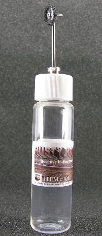
It's kind of a nifty little tool - basically a squeeze bottle that squirts paint up through a little tube and on to a rolling wheel - thus allowing you to roll it along the sides of the rails and paint them. And I guess I was thinking that since I wanted to try painting my rails a different color than the ties, I'd give it a try.
I started by experimenting around with it on a piece of track using their "rust" colored paint, but decided that that color just plain looked weird. And as I was in the process of switching to brown paint, it dawned on me - if I'm going to be painting the rails basically the same color as the ties, why am I wasting my time with this tool? So, I grabbed my can of Roof Brown spray paint and finished the job that way instead (spraying at an angle from either side to hit the rails, as opposed to the "straight down" spray I used to paint the ties).
So, I dunno. It (the rusty rail painter) is kind of an interesting idea. But for my purposes, I can get decent enough results a lot quicker and easier simply using a can of spray paint.
So, that's that. Next up - a riot ensues as I try to cram every single resident of Slackjaw into a single mobile home.
03/29/08 - Finished the trailer
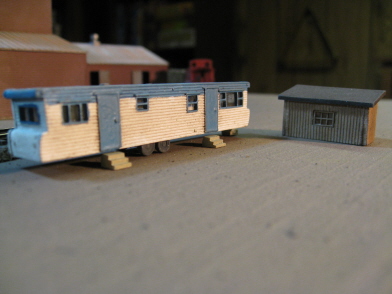
I add this structure to my layout in honor of all those "northern Minnesota trailer guys". Guys who, faced with 10,000 lakes from which to choose, instead opt for plunking their crummy little mobile homes next to the highway out in the middle of nowhere (and then spend the rest of their lives filling up their yards with derelict automobiles and other assorted junk). This particular yahoo even went so far as to park his crib next to the railroad tracks... you go, guy!
The trailer kit itself came from NuComp Miniatures, and sadly, is constructed out of resin - IE, get your CA ready, you're in for a bumpy ride. Unfortunately, NuComp seems to be the only game in town when it comes to trailers, so what are you gonna do? The good news (for people really into trailers) is that NuComp offers a wide assortment - enough, in fact, to put together an entire trailer park.
I can't say that my paint and assembly job turned out particularly "ept", but given that we're talking about "northern Minnesota trailer guy", I suppose you could say I pretty much nailed the prototype. I also picked up that shed "thing" from NuComp, and I'm even less pleased with the results on that one than I am with the trailer. I figured NMTG needed someplace to store his crud (or at least the crud not stored in his yard), but this particular building isn't doing much for me. Maybe I'm hating on it because it was such a bitch to assemble (seriously, at one point I actually tossed it into the trash in a fit of CA-fueled disgust). So, I dunno. Right now I'm not even sure if I'm going to actually use it... we'll see, I guess.
Not surprisingly, Slackjaw still feels woefully lacking as far as places for people to live are concerned. So, I think I need to add one more building (a house this time) off the road into town. Hopefully that'll do.
It's probably become obvious that I'm procrastinating here - unable to motivate myself to get going on the scenery. I guess my problem there is that I'm not entirely sure how to proceed. Unfortunately, the Kootenay plan doesn't provide much in the way of guidance. Basically it's a track plan and a couple of drawings of the town area. As for the areas outside of town, well... apart from the topographical map, there just isn't much to go on. Honestly, you'd think somebody somewhere must've actually built this layout at some point. So, why not include a couple of photographs with the article?
Part 3 - Roads, lighting and scenery (and yet more buildings)
Part 4 - Scenery, detailing (and yet more lighting)
Part 5 - Trees, detailing, and the end of the line